This guide is for the 2600 “Light Sixer” 6-switch PAL model – if you have a different model 2600, this guide may vary. Please compare the photos below to your board. Check the 2600 mod guide main page for other models that I have guides available for!
Step 1 – crack ‘er open
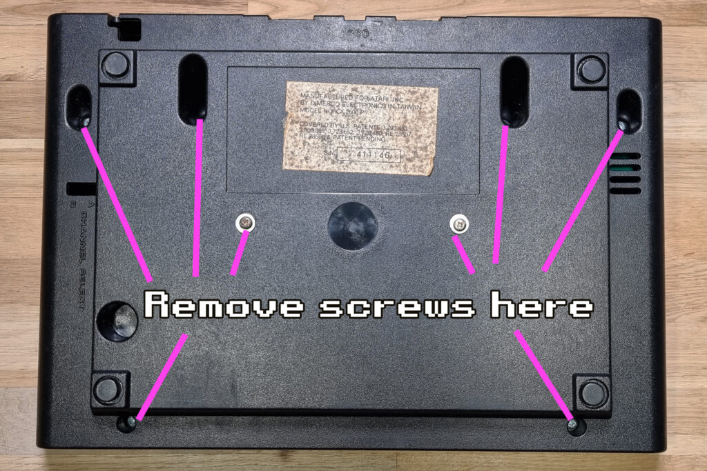
First step is, quite obviously, remove the mainboard from your 2600. There are eight screws on the bottom of the case and the top should just lift off, and the mainboard should come right out.
Step 2a – free controls from can
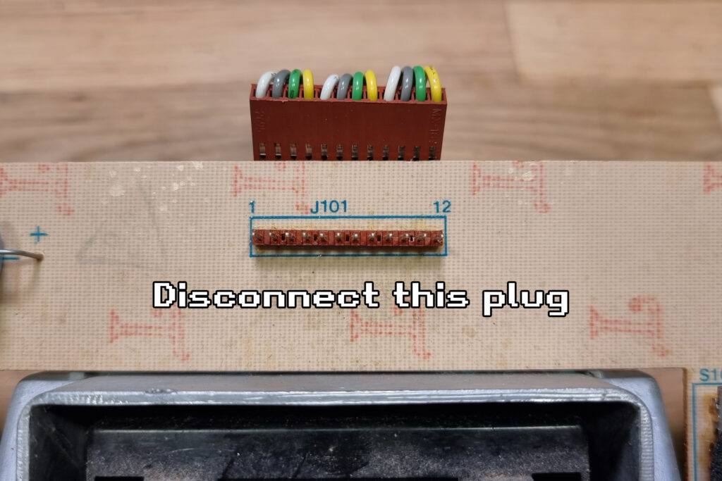
Once you have the guts out, we need to remove the main board (inside the metal can) from the sub-board that contains the switches and power components. Start by removing this plug
Step 2b – remove can
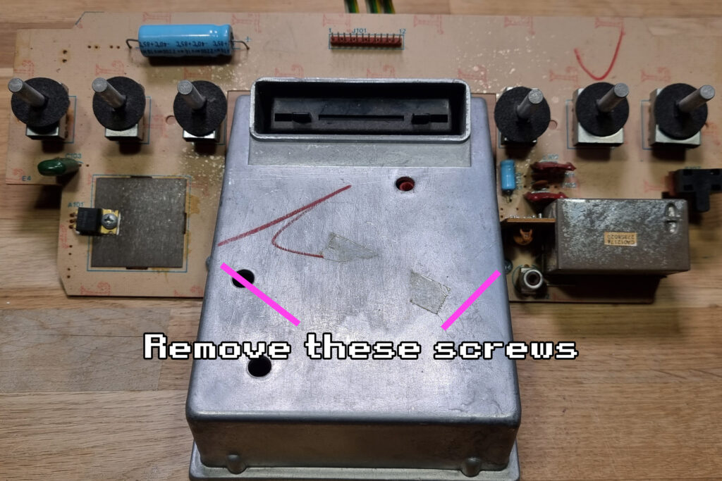
Then remove these two screws that hold the two parts together, and separate them.
Step 2c – open can
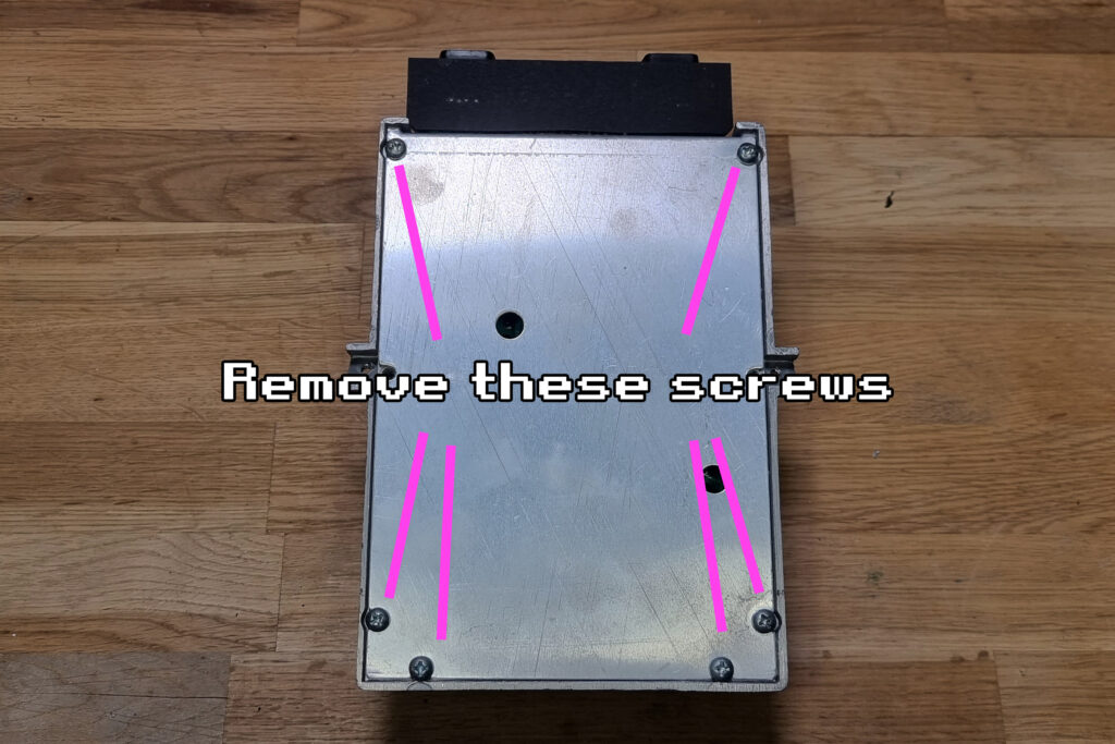
Now the two parts are separated, we need to extract the mainboard from the can. Start by removing the six screws on the bottom of the can.
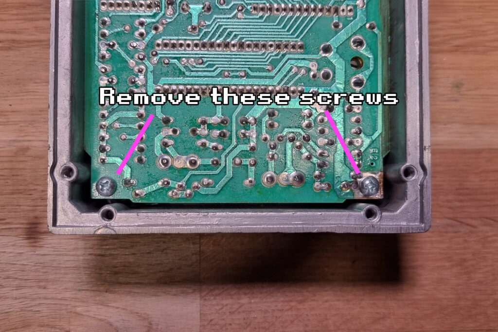
Step 2d – free mainboard
And then remove these two screws which will finally free the mainboard.
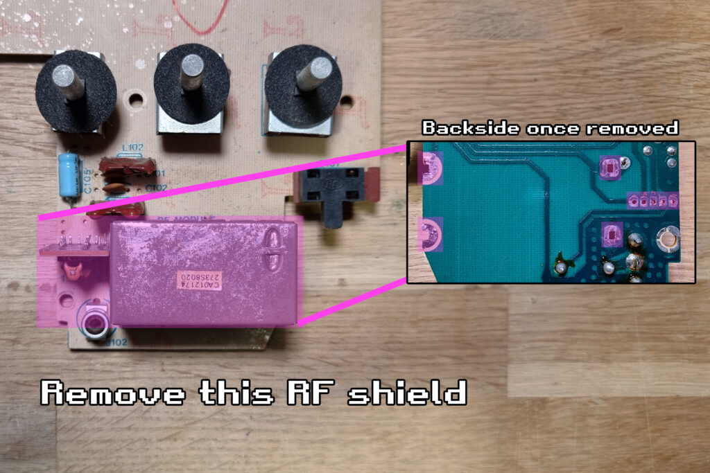
Step 3 – remove old RF module
Next up you will want to remove a few components. Warm up your soldering iron – we’re going in!
Here you will need to remove the existing RF modulator on the board. It’s the big box in the bottom right of the sub-board. Desolder and remove the whole unit, and optionally the previous antenna cable jack.
You can see below which specific solder joints on the back you need to desolder to get the RF shield off.
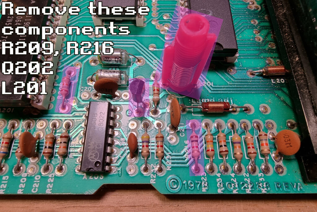
Step 4 – remove old components
Then you will need to remove two resistors, one transistor, and one inductor – R209, R216, Q202, and L201. You can desolder them however you like. If you’re not too confident, just snip the leads off and remove them.
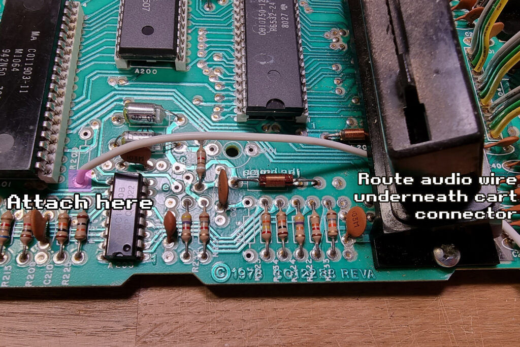
Step 5a – route and connect audio wire
Unlike the other wires, the audio wire is connected directly to the mainboard here. Start by routing the wire underneath the cartridge connector as shown, and then connect it to one of the removed pins from R209
Step 5b – button it up
Once that wire is connected, you can place the mainboard back in the can and reassemble the main bulk of the guts – just follow step 2 in reverse.
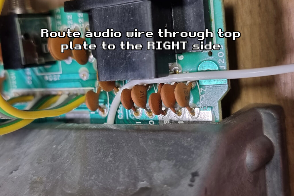
Make sure to route the audio wire out the top of the can using the gap, and then to the right-hand side.
Step 6 – the rest of the owl
Now you can connect the other wires from the mod board to the remaining three points on the switch board. They go into the pin holes freed up from removing the RF module. On the pre-assembled mods we provide, the wire colours are always as shown in the photo below: ground is black, power is red, video is yellow, audio is white.
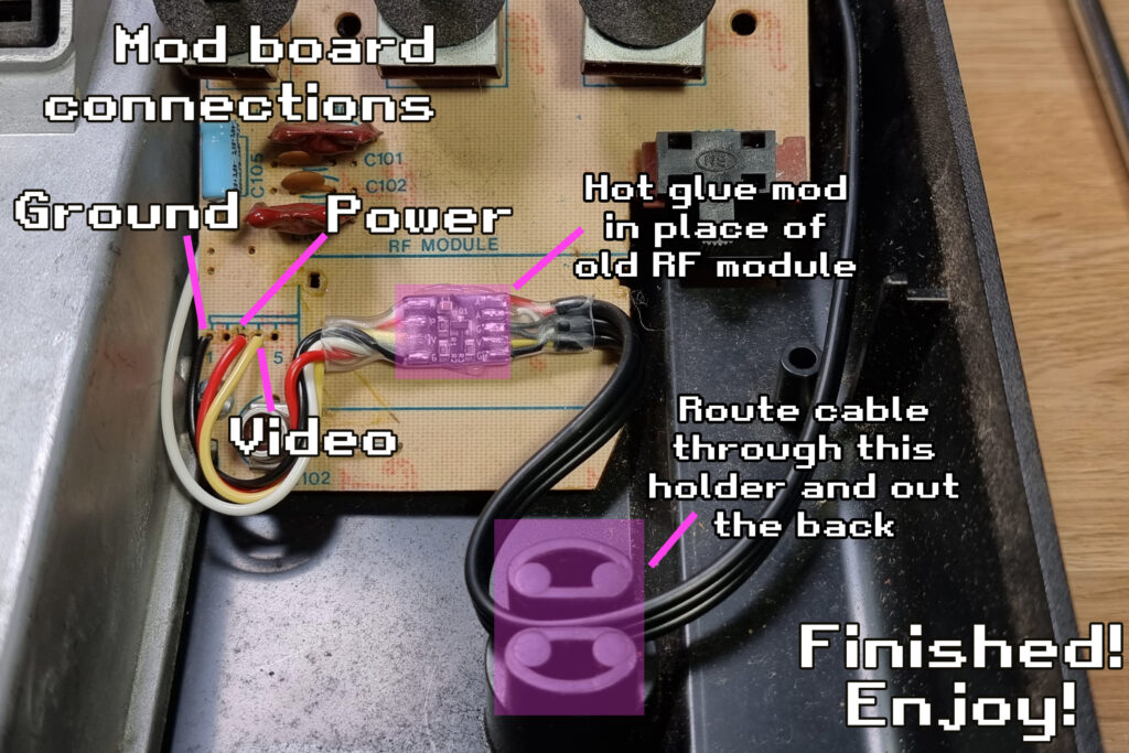
Once all the wires are soldered, you can secure the board using some hot glue in place of where the RF module once was. Route the bulk of the cable through the strain relief in the 2600 and out the hole in the back.
All done!
Enjoy your new-old Atari 2600 connected via composite to your new/old TV!