Why?
One of the most common failures on Commodore 64 units is failure of the PLA or Programmable Logic Array chip. It’s one of the most critical components in the C64, once described by Commodore engineer James Redfield as “glue logic to tie everything together.”
There has been a number of speculations as to why these have such a high failure rate, and I’m not going into the specifics here, but needless to say if you’re either trying to revive your old unit that’s been in your attic for decades, or fixing a not-insignificant number of Commodores, you’ll no doubt have to replace at least one of these.
Thanks to a thriving community of enthusiasts, there have popped up a number of modern like-for-like replacements of the original PLA in the last decade or so, such as the PLAnkton and PLA20V8.
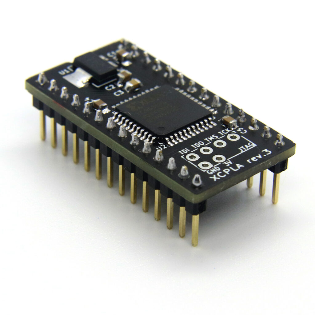
The one we have decided to stock in our store is the XCPLA by hackup, as shown below.
Installing
So you’ve determined your PLA is faulty and you’ve decided to pick up an XCPLA or similar replacement. Now comes the question, how do you install it?
First of all, you will need some fearlessness – this will require you to open up your retro hardware and tinker around inside, but I’m assuming you already know this so moving on.
Secondly, it may require some soldering skills and tools. A lot of C64 units these days will already have the PLA chip in an IC socket on the mainboard, however yours may not. This will require you to remove your faulty PLA from the board and, ideally, solder in an IC socket in which to place your XCPLA. I’m not going to go into detail on how to do this as there are plenty of desoldering guides on the internet – my choice being this one from retro64.
Steps
Open up your Commodore and locate the U17 chip. In an SX-64 the PLA will be designated UE4.
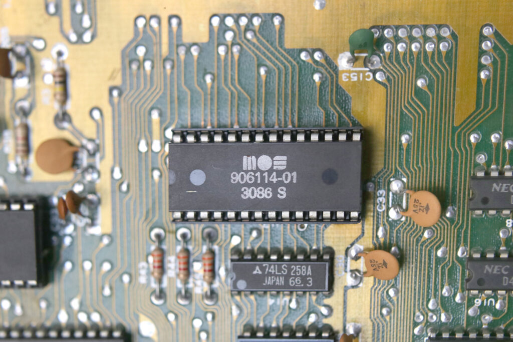
It is important here to verify the chip you have located is NOT the SID chip. Ensure the markings on the chip, as shown in the photo above, match one of the following: 82S100, 93459PC, 7700, 8700, 906114-01, 251064-01.
In the above photo, you can see the chip itself has a small semi-circle indentation to the far left – this indicates the PLA’s orientation. You will need to note which side this is on for later.
If your old PLA is already in a socket, gently pry it out of the socket. Easiest way to do this is with the tip of a wide, flat screw driver, inserted between the chip and the IC socket at the long edge. Be very careful not to go in too deep under the chip, as you may scratch and damage the traces on the mainboard underneath it!
If your board does not have the PLA in a socket, here is where you will need to remove it by whatever desoldering technique you have in your repertoire. Once you have the chip removed, you can place the new IC socket in the pin holes on the board and solder it in place, remembering to place the notch in the IC socket in the same orientation as the PLA you removed.
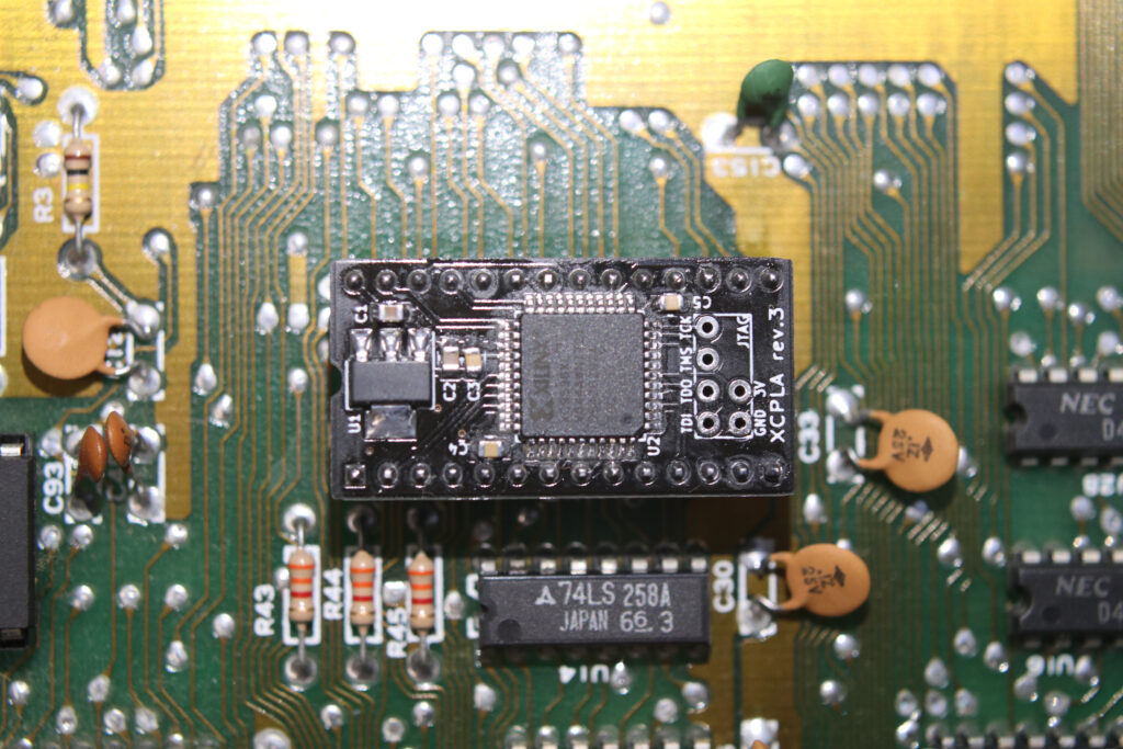
Now that you have an empty socket on the board, you can gently press the XCPLA board down into the socket pins, noting the notch on the XCPLA should match the same as the PLA chip you pulled out, and the notch on the IC socket, as shown above.
Test it!
That’s it! Your install is complete and your C64 should be ready to test. Put it all back together, hook up the video output and power and flick on the switch – if all goes well (and that was the only issue!) your old beauty should spring to life.
I hope this short guide has helped you with your install. If you’d like to buy an XCPLA, you can find them in our store.
If you’re still on the fence about whether you want to tackle this particular install, or you’ve attempted the install and run into problems, we also offer a full repair service and can do the work for you.
Happy repairing!